Securely Connecting a MKR GSM 1400 to Google Cloud IoT Core
In this tutorial, you'll learn how to connect your Arduino MKR GSM 1400 board securely to Google Cloud Platform (GCP) IoT Core.
Components and Supplies
- Arduino MKR GSM 1400
- Micro-USB to USB Cable (Generic)
- 3.7V Lipo Battery
- Micro SIM card
- Cellular UF.L Antenna
Apps and Online Services
About This Project
Introduction
Cloud IoT Core is a fully managed service that allows you to easily and securely connect, manage, and ingest data from millions of globally dispersed devices. Cloud IoT Core, in combination with other services on Cloud IoT platform, provides a complete solution for collecting, processing, analyzing, and visualizing IoT data in real time to support improved operational efficiency.
Devices can connect to GCP IoT Core using HTTP or MQTT. This tutorial will walk you through how to connect an Arduino MKR GSM 1400 board securely to GCP IoT Core using an MQTT client. MQTT (Message Queuing Telemetry Transport) is a M2M (machine-to-machine) connectivity protocol which provides a messaging subscription and publish transport.
Devices must use JSON Web Tokens (JWTs) for authentication, more information on JWTs can be found in RFC 7519. GCP IoT Core supports both RSA and Elliptic Curve algorithms to verify JSON Web Signatures (JWS). More information on JWS can be found in RFC 7515.
Every Arduino MKR board with on-board connectivity, including the MKR GSM 1400, is equipped with a Microchip ATECC508A or ATECC608A crypto element. This crypto element can be used to securely generate and store a 256-bit ECC (Elliptic Curve Cryptography) key. We'll be using a private key stored inside the crypto element to sign the JWT.
Software and Hardware Setup
If you don't have the Arduino IDE installed on your computer, download and install it.
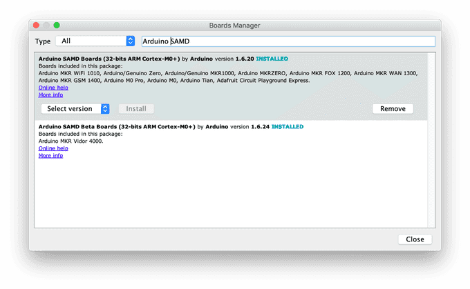
Once it is installed, make sure you have the latest "Arduino SAMD Boards" package installed. You can check by opening the Arduino IDE, and opening the Tools -> Board: "..." -> Board Manager... menu entry, and searching for "Arduino SAMD". At the time of writing 1.6.20 was the latest version.
Next you'll need to install the Arduino libraries that will be used, using the Arduino IDE's library manager. Open Sketch -> Include Library -> Manage Libraries.. menu, search for and individually install each of the following libraries:
- MKRGSM
- Arduino_JSON
- ArduinoECCX08 (version 1.3.0 or later)
- ArduinoMqttClient (version 0.1.3 or later)
- Arduino Cloud Provider Examples (version 1.2.0 or later)
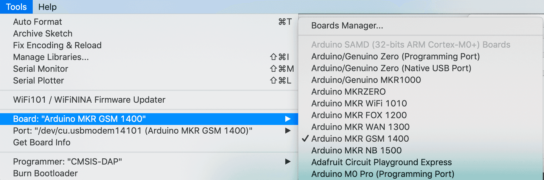
Now insert the micro SIM card in the slot on the bottom of the MKR GSM 1400 board, connect the antenna, and attach the 3.7V Lipo battery to the JST PH connector. Then plug in the MKR GSM 1400 with the micro USB cable to your computer, select the serial port in the Arduino IDE using the Tools -> Port "..." menu and also select Arduino MKR GSM 1400 in the Tools -> Board "..." menu.
Configuring and Adding the Board to GCP IoT Core
As mentioned above, GCP IoT Core requires devices that connect using the MQTT protocol to use JWT for authentication. We'll use a sketch to generate a private and public key on the board, then add the PEM value of the public key to the GCP IoT Core console.
The private and public can be generated using an example sketch from the ArduinoECCX08 library. Open the sketch in the Arduino IDE using the File -> Examples -> ArduinoECCX08 -> Tools -> ECCX08JWSPublicKey. Click the "Upload" button to build and upload the sketch to your board, then open the Serial Monitor. Make sure the line ending configuration is set to "Both NL & CR."
This sketch will prompt you to permanently configure your ATECC508A to ECC608A crypto element if it is not configured and locked.
NOTE: This locking process is permanent and irreversible, but is needed to use the the crypto element - the configuration the sketch sets allows you to use 5 private key slots with any Cloud provider(or server) and a private key can be regenerated any time for any of the 5 private key slots (0 - 4).
When the board is shipped from the factory, the crypto element is in an unconfigured and unlocked state.
After this, you will be prompted for what slot to use. For this tutorial we'll be using slot 0 to generate and store the private key used for a public key (slots 1 to 4 can be used to generate and store additional private keys if needed). Note: Since the private key is generated inside the crypto element it never leaves the device and is stored securely and cannot be read.
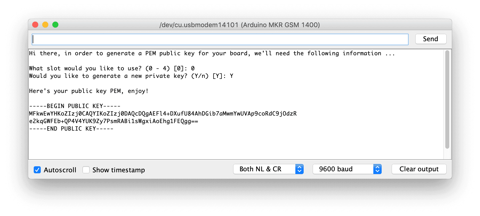
Copy the generated public key value, in this screenshot the value is:
1-----BEGIN PUBLIC KEY-----2MFkwEwYHKoZIzj0CAQYIKoZIzj0DAQcDQgAEFl4+DXufU84AhDGib7aMwmYwUVAp9coRdC9jOdzR3e2kqGWFEb+QP4V4YUK9Zy7PsmRABi1sWgxiAoEhg1FEQgg==4-----END PUBLIC KEY-----We will use it in a later step when adding the device to GCP IoT Core.
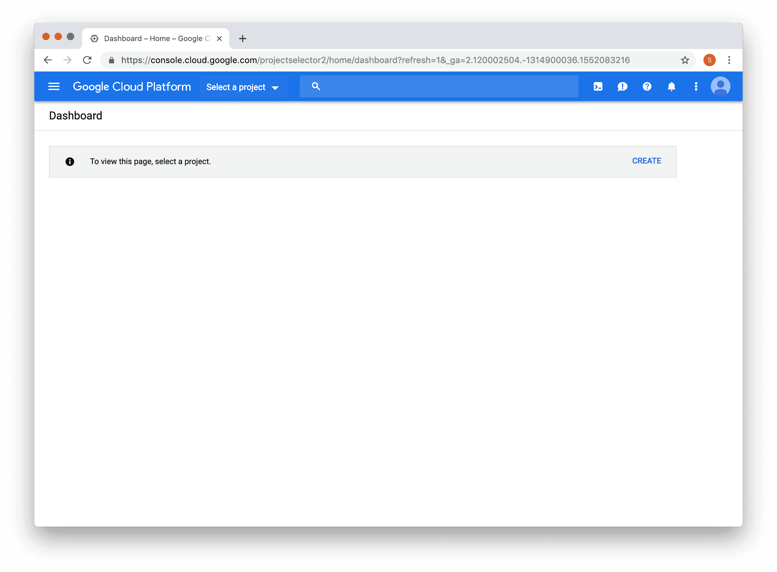
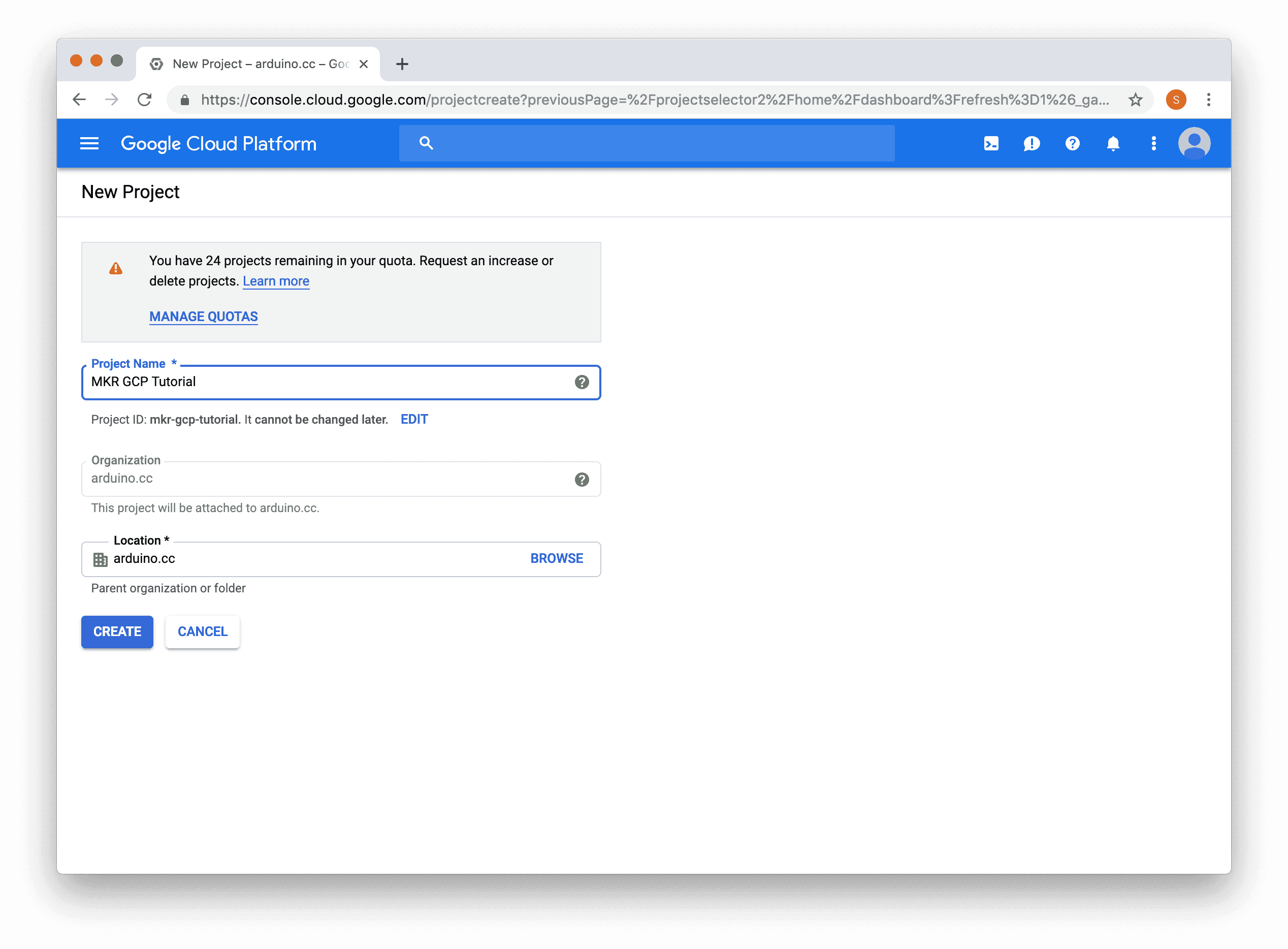
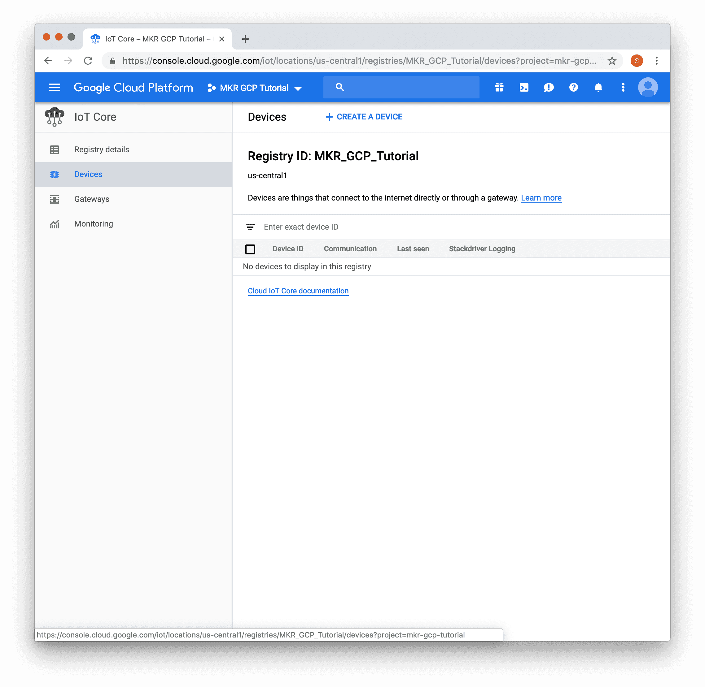
Now that we have a PEM public key, we need to login into the GCP IoT Core console and create a new device for it.
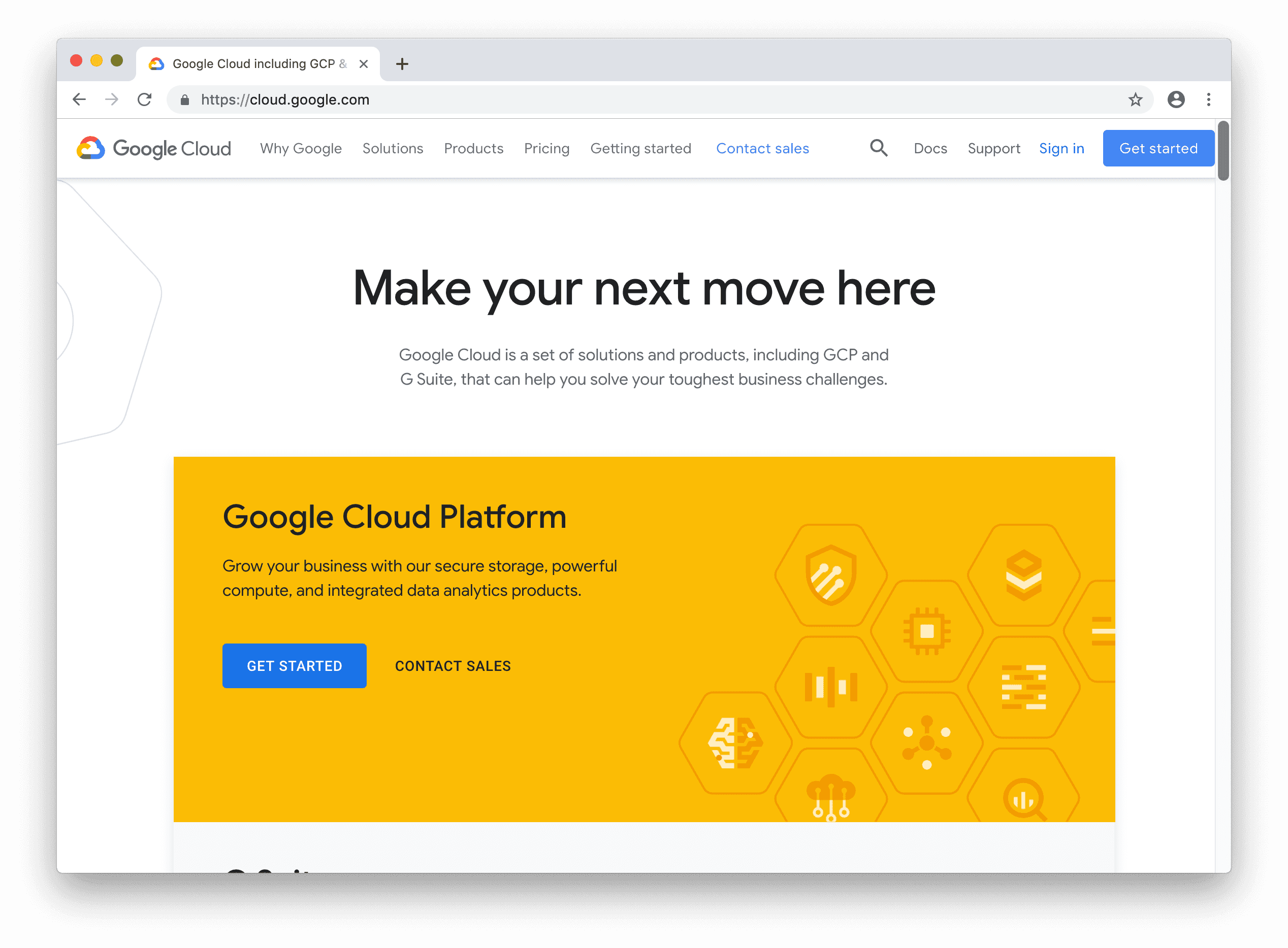
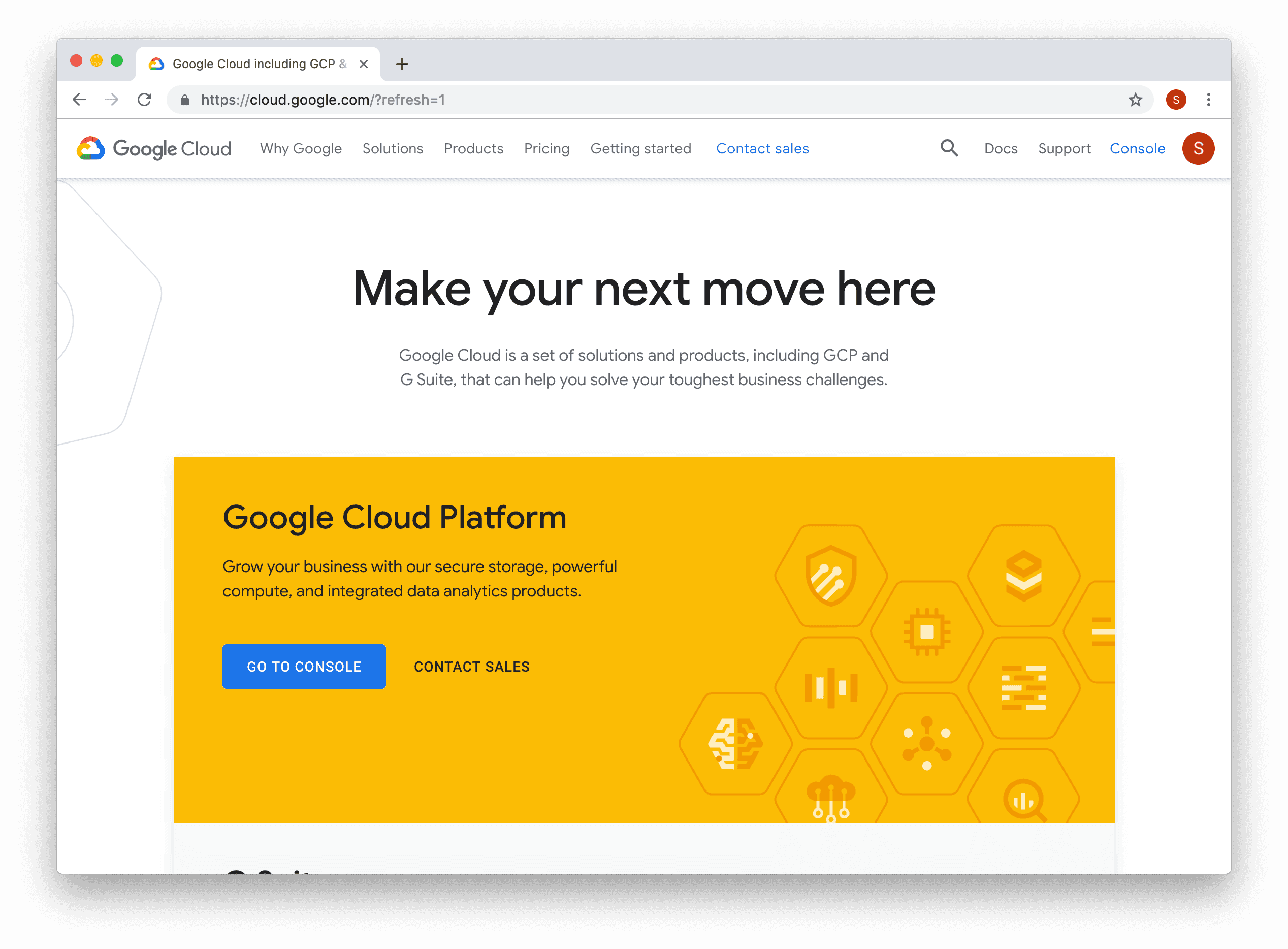
Open a web browser and go to https://cloud.google.com/ and click the "Sign In" link to login with your Google ID.
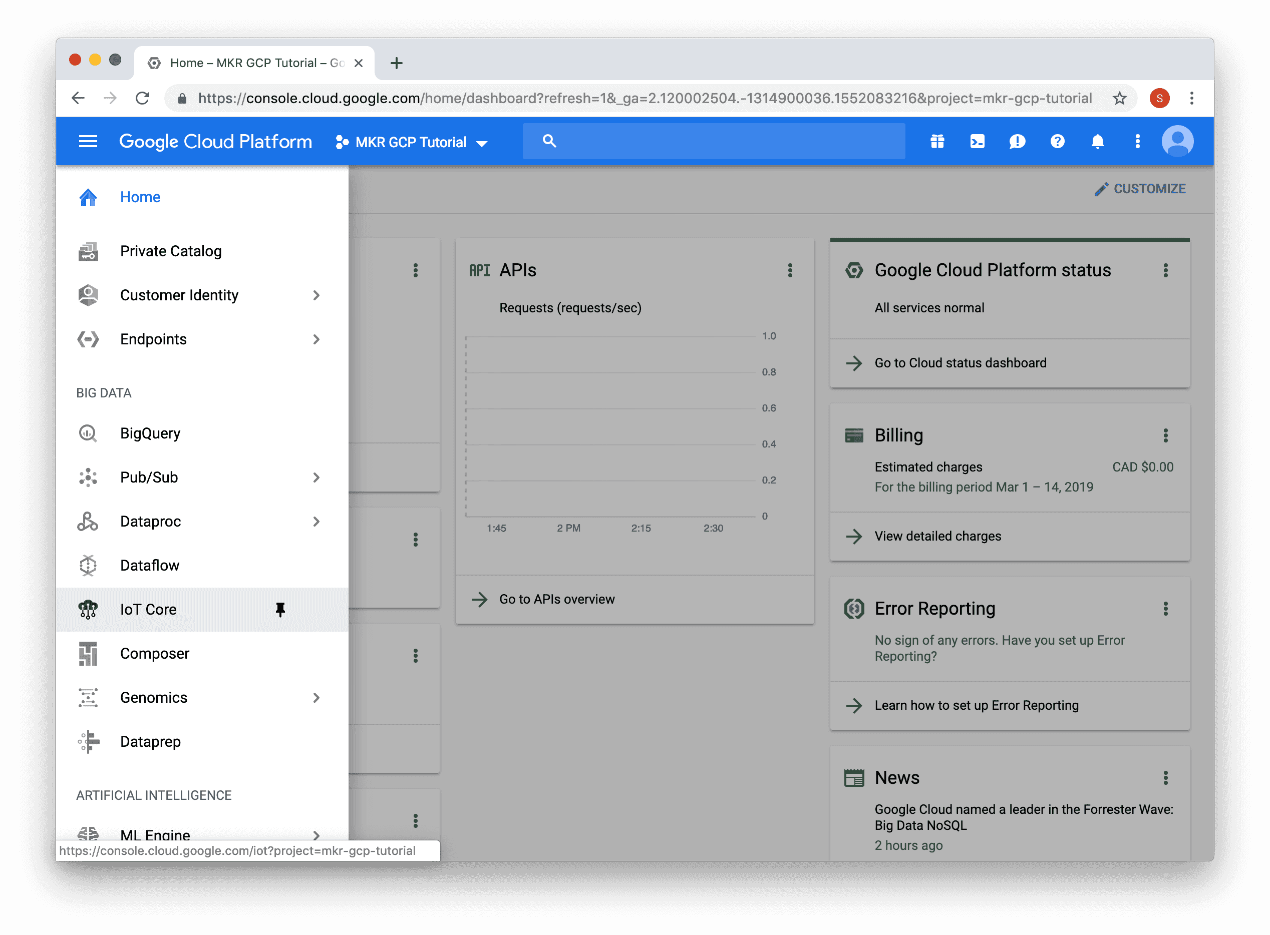
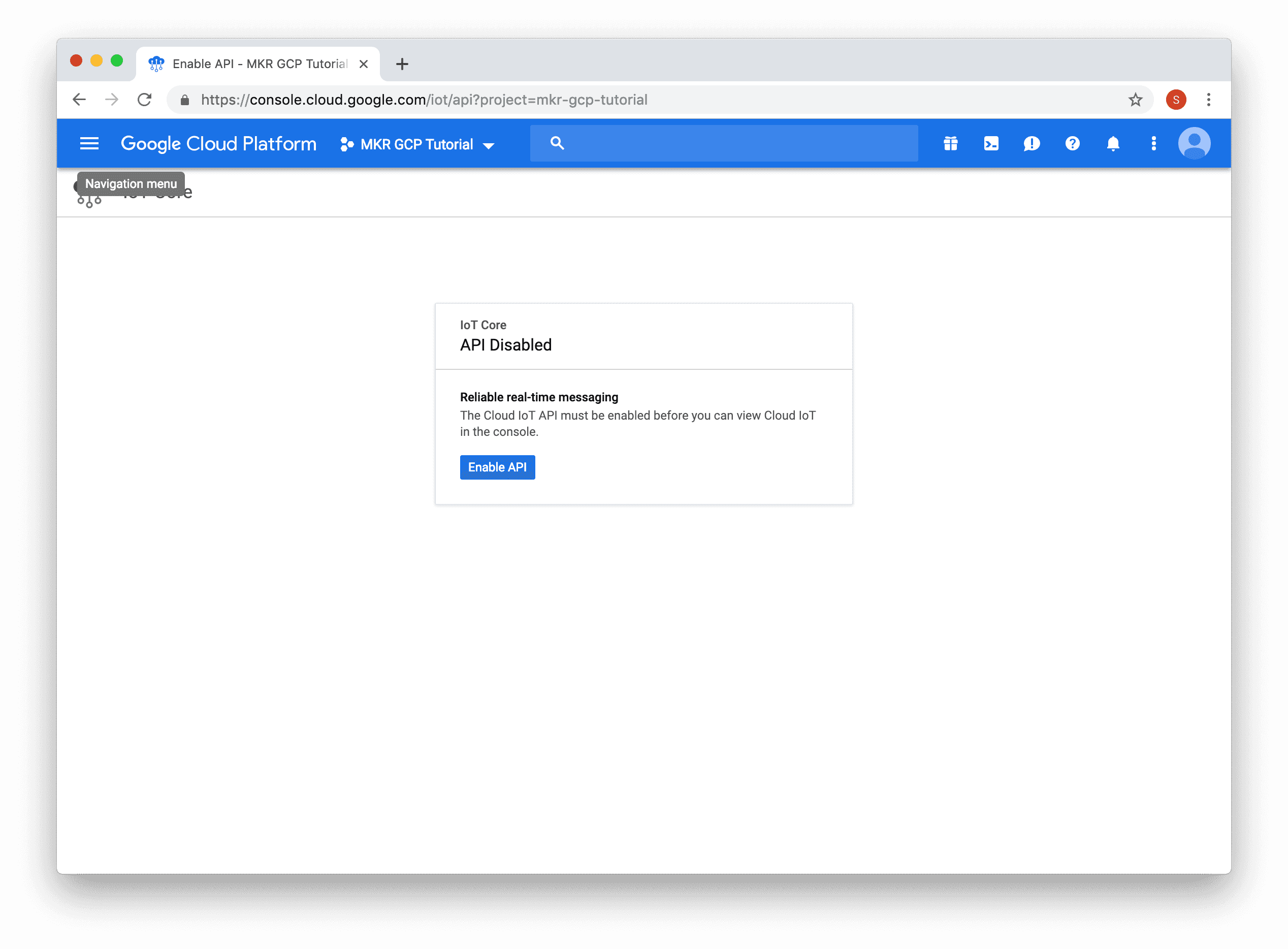
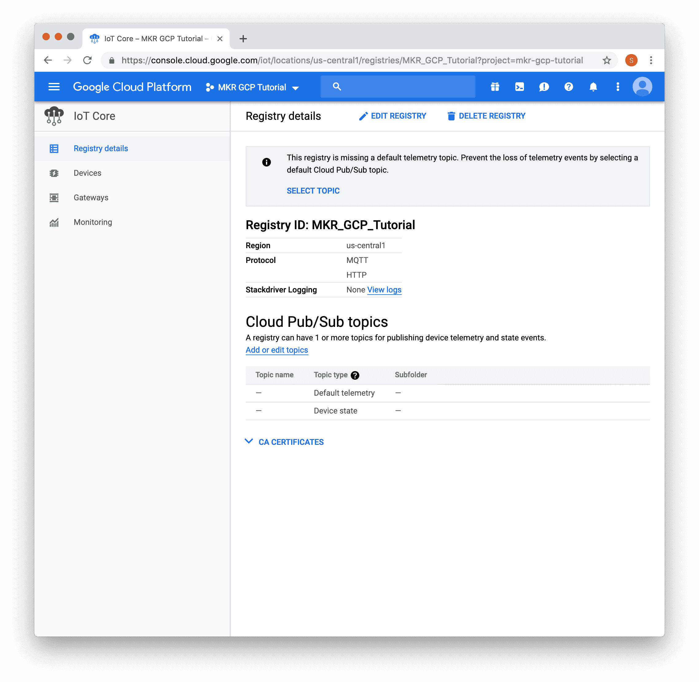
Once the API is enabled, you will be prompted to create a device registry.
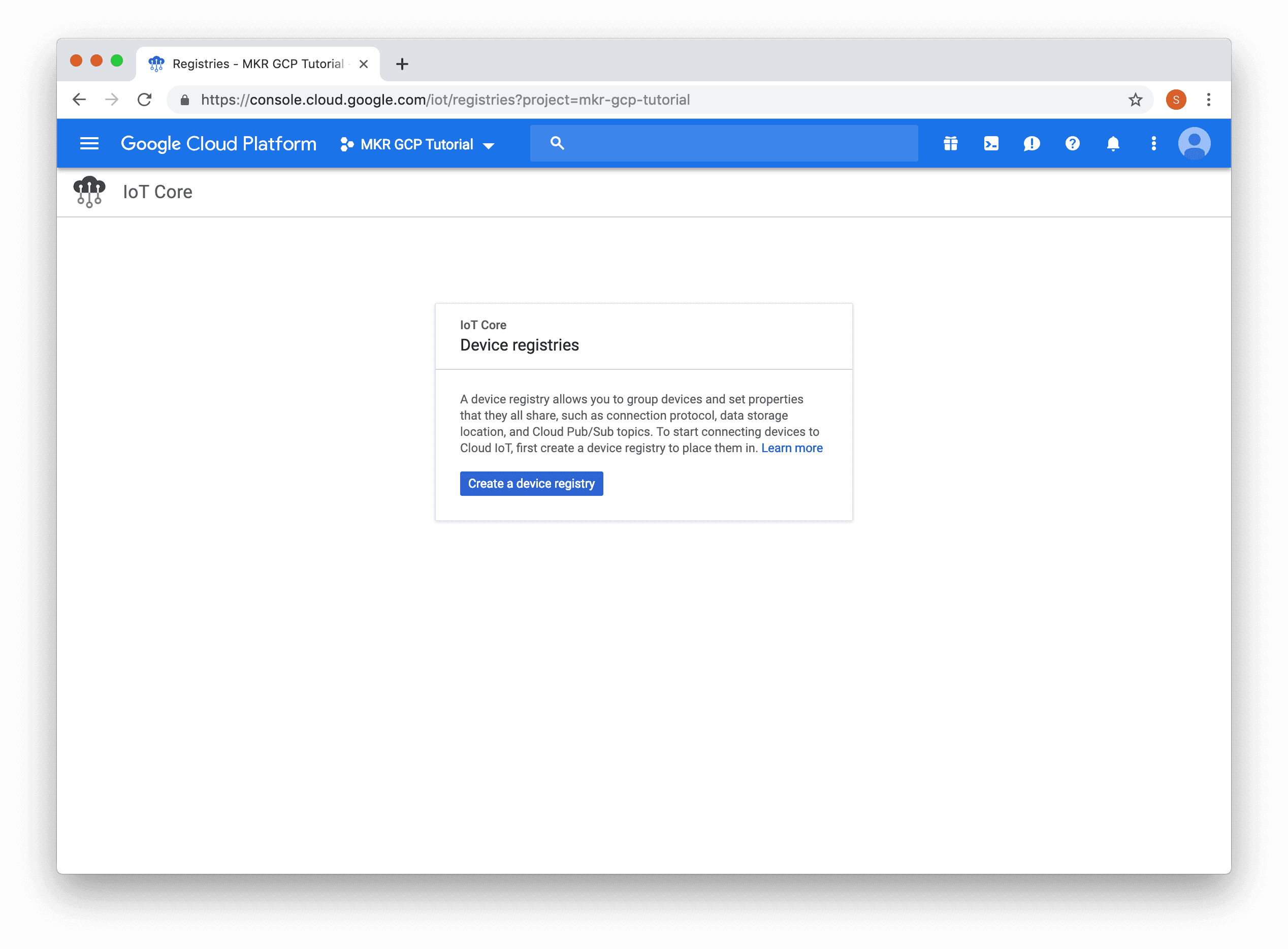
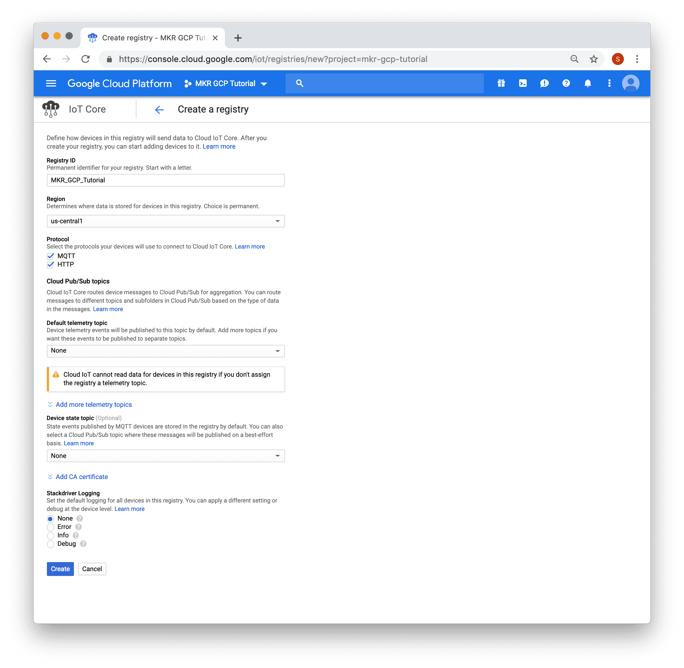
You will then be presented with a form. Fill in the "Registry ID", select a region. In the screenshot below "MKR_GCP_Tutorial" was entered for the registry ID and "us-central1" was selected as the region. After the form has been filled in, click the "Create" button.

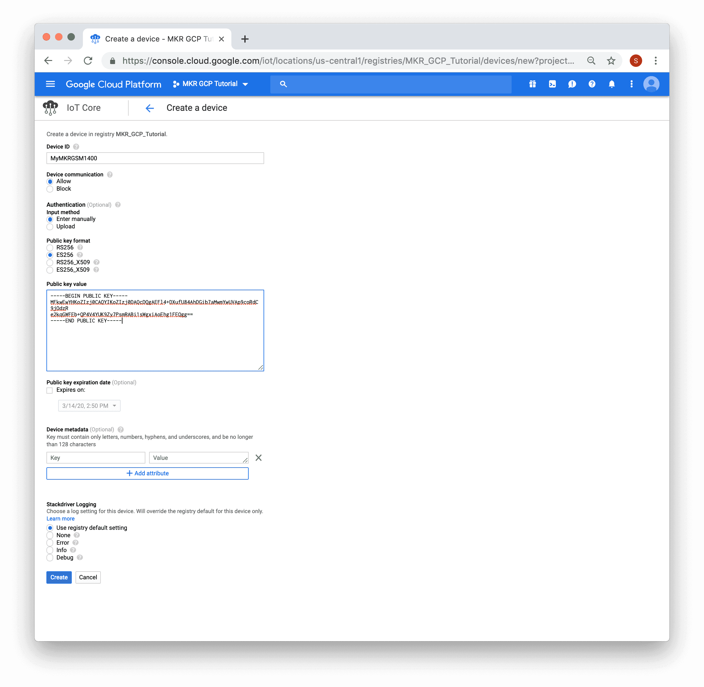
Enter the device name, in the screenshot below "MyMKRGSM1400" was used. "ES256" must be selected as the "Public key format". Paste the PEM public key generated on the board earlier into the "Public key value" text area. Then click the "Create" button.
Connecting the Board to GCP IoT Core
1) Open the GCP IoT Core GSM sketch in the Arduino IDE using File -> Examples ->Arduino Cloud Provider Examples -> GoogleCloudPlatformIoTCore->GCP_IoT_Core_GSM.
2) In the arduino_secrets.h tab, fill in the pin (if required) for the SIM card, as well as the GPRS APN, username and password for the cellular carrier you are using.
1// GSM settings2#define SECRET_PINNUMBER ""3#define SECRET_GPRS_APN "GPRS_APN" // replace your GPRS APN4#define SECRET_GPRS_LOGIN "login" // replace with your GPRS login5#define SECRET_GPRS_PASSWORD "password" // replace with your GPRS password4) Then update the project id, Cloud region, registry id and device id values.
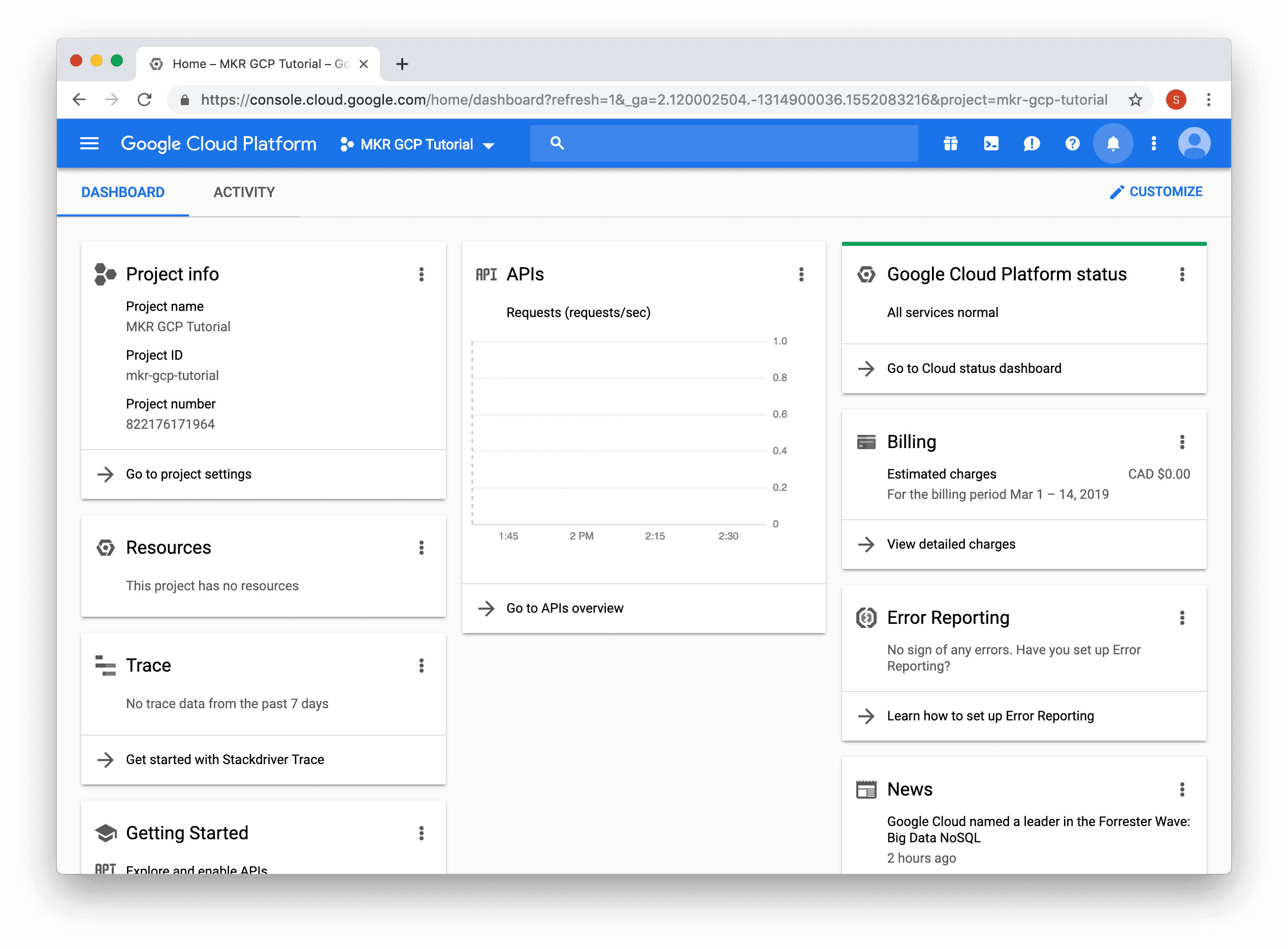
1// Fill in your Google Cloud Platform - IoT Core info2#define SECRET_PROJECT_ID ""3#define SECRET_CLOUD_REGION ""4#define SECRET_REGISTRY_ID ""5#define SECRET_DEVICE_ID ""The project id value can be found by clicking the menu bar at the top of the GCP console. For the steps above the values are:
1#define SECRET_PROJECT_ID "mkr-gcp-tutorial"2#define SECRET_CLOUD_REGION "us-central1"3#define SECRET_REGISTRY_ID "MKR_GCP_Tutorial"4#define SECRET_DEVICE_ID "MyMKRGSM1400"5) Upload the sketch below to your board and open the serial monitor. The board will attempt to connect to the cellular network and if successful try to connect to GCP IoT Core using MQTT.
Complete Sketch
1/*2 GCP (Google Cloud Platform) IoT Core GSM3 This sketch securely connects to GCP IoT Core using MQTT over GSM/3G.4 It uses a private key stored in the ATECC508A and a JSON Web Token (JWT) with5 a JSON Web Signature (JWS).6 It publishes a message every 5 seconds to "/devices/{deviceId}/state" topic7 and subscribes to messages on the "/devices/{deviceId}/config" and8 "/devices/{deviceId}/commands/#" topics.9 The circuit:10 - MKR GSM 1400 board11 - Antenna12 - SIM card with a data plan13 - LiPo battery14 This example code is in the public domain.15*/16
17#include <ArduinoECCX08.h>18#include <utility/ECCX08JWS.h>19#include <ArduinoMqttClient.h>20#include <Arduino_JSON.h>21#include <MKRGSM.h>22
23#include "arduino_secrets.h"24
25/////// Enter your sensitive data in arduino_secrets.h26const char pinnumber[] = SECRET_PINNUMBER;27const char gprs_apn[] = SECRET_GPRS_APN;28const char gprs_login[] = SECRET_GPRS_LOGIN;29const char gprs_password[] = SECRET_GPRS_PASSWORD;30
31const char projectId[] = SECRET_PROJECT_ID;32const char cloudRegion[] = SECRET_CLOUD_REGION;33const char registryId[] = SECRET_REGISTRY_ID;34const String deviceId = SECRET_DEVICE_ID;35
36const char broker[] = "mqtt.googleapis.com";37
38GSM gsmAccess;39GPRS gprs;40
41GSMSSLClient gsmSslClient;42MqttClient mqttClient(gsmSslClient);43
44unsigned long lastMillis = 0;45
46void setup() {47 Serial.begin(9600);48 while (!Serial);49
50 if (!ECCX08.begin()) {51 Serial.println("No ECCX08 present!");52 while (1);53 }54
55 // Calculate and set the client id used for MQTT56 String clientId = calculateClientId();57
58 mqttClient.setId(clientId);59
60 // Set the message callback, this function is61 // called when the MQTTClient receives a message62 mqttClient.onMessage(onMessageReceived);63}64
65void loop() {66 if (gsmAccess.status() != GSM_READY || gprs.status() != GPRS_READY) {67 connectGSM();68 }69
70 if (!mqttClient.connected()) {71 // MQTT client is disconnected, connect72 connectMQTT();73 }74
75 // poll for new MQTT messages and send keep alive76 mqttClient.poll();77
78 // publish a message roughly every 5 seconds.79 if (millis() - lastMillis > 5000) {80 lastMillis = millis();81
82 publishMessage();83 }84}85
86unsigned long getTime() {87 // get the current time from the cellular module88 return gsmAccess.getTime();89}90
91void connectGSM() {92 Serial.println("Attempting to connect to the cellular network");93
94 while ((gsmAccess.begin(pinnumber) != GSM_READY) ||95 (gprs.attachGPRS(gprs_apn, gprs_login, gprs_password) != GPRS_READY)) {96 // failed, retry97 Serial.print(".");98 delay(1000);99 }100
101 Serial.println("You're connected to the cellular network");102 Serial.println();103}104
105void connectMQTT() {106 Serial.print("Attempting to connect to MQTT broker: ");107 Serial.print(broker);108 Serial.println(" ");109
110 while (!mqttClient.connected()) {111 // Calculate the JWT and assign it as the password112 String jwt = calculateJWT();113
114 mqttClient.setUsernamePassword("", jwt);115
116 if (!mqttClient.connect(broker, 8883)) {117 // failed, retry118 Serial.print(".");119 delay(5000);120 }121 }122 Serial.println();123
124 Serial.println("You're connected to the MQTT broker");125 Serial.println();126
127 // subscribe to topics128 mqttClient.subscribe("/devices/" + deviceId + "/config", 1);129 mqttClient.subscribe("/devices/" + deviceId + "/commands/#");130}131
132String calculateClientId() {133 String clientId;134
135 // Format:136 //137 // projects/{project-id}/locations/{cloud-region}/registries/{registry-id}/devices/{device-id}138 //139
140 clientId += "projects/";141 clientId += projectId;142 clientId += "/locations/";143 clientId += cloudRegion;144 clientId += "/registries/";145 clientId += registryId;146 clientId += "/devices/";147 clientId += deviceId;148
149 return clientId;150}151
152String calculateJWT() {153 unsigned long now = getTime();154
155 // calculate the JWT, based on:156 // https://cloud.google.com/iot/docs/how-tos/credentials/jwts157 JSONVar jwtHeader;158 JSONVar jwtClaim;159
160 jwtHeader["alg"] = "ES256";161 jwtHeader["typ"] = "JWT";162
163 jwtClaim["aud"] = projectId;164 jwtClaim["iat"] = now;165 jwtClaim["exp"] = now + (24L * 60L * 60L); // expires in 24 hours166
167 return ECCX08JWS.sign(0, JSON.stringify(jwtHeader), JSON.stringify(jwtClaim));168}169
170void publishMessage() {171 Serial.println("Publishing message");172
173 // send message, the Print interface can be used to set the message contents174 mqttClient.beginMessage("/devices/" + deviceId + "/state");175 mqttClient.print("hello ");176 mqttClient.print(millis());177 mqttClient.endMessage();178}179
180void onMessageReceived(int messageSize) {181 // we received a message, print out the topic and contents182 Serial.print("Received a message with topic '");183 Serial.print(mqttClient.messageTopic());184 Serial.print("', length ");185 Serial.print(messageSize);186 Serial.println(" bytes:");187
188 // use the Stream interface to print the contents189 while (mqttClient.available()) {190 Serial.print((char)mqttClient.read());191 }192 Serial.println();193
194 Serial.println();195}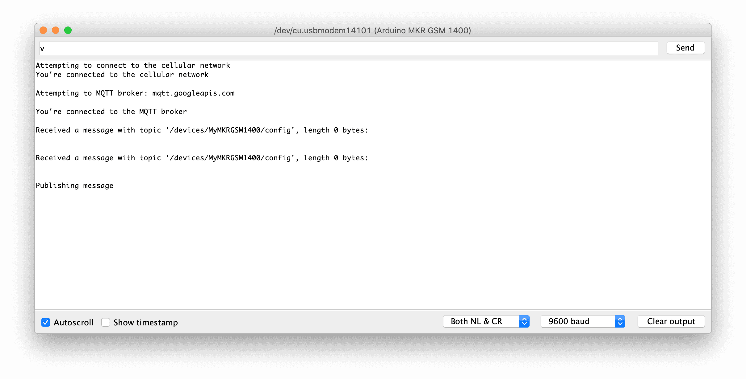
Interacting with the Board on GCP IoT Core
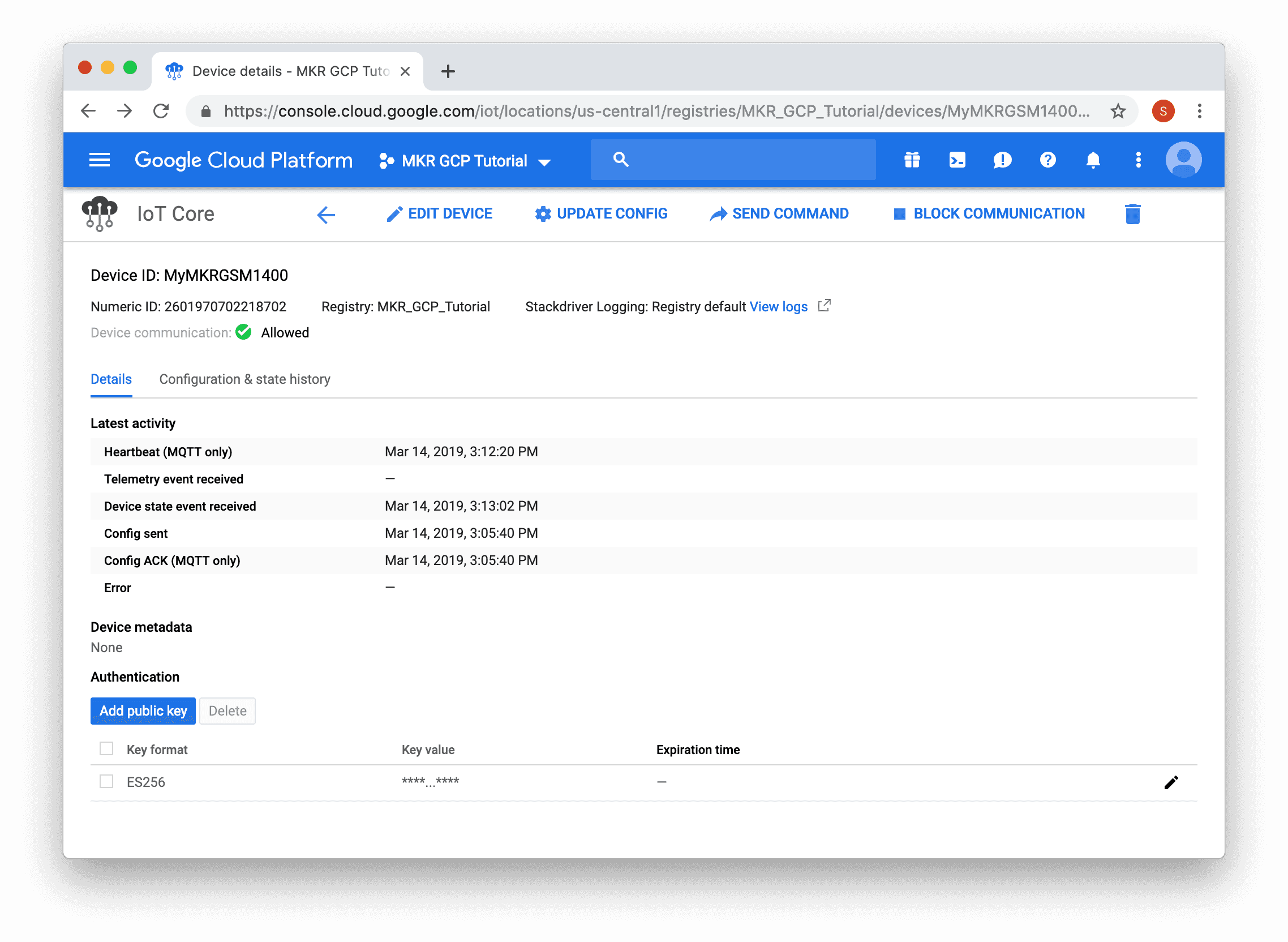
Now that your board has successfully connected to GCP IoT Core, we can use the GCP IoT Core console to interact with it. The sketch sends a message to the /devices/{deviceId}/state topic every 5 seconds and listens for messages on both /devices/{deviceId}/config topic and /devices/{deviceId}/commands/# topics.
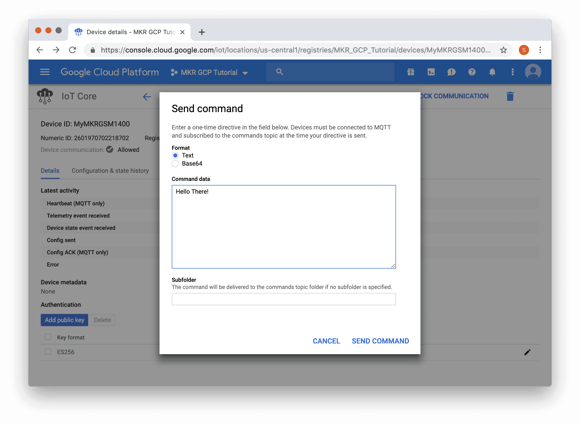
A modal dialog will appear, where you can enter a message to send. In the screenshot below "Hello There!" was entered. Click the "SEND COMMAND" button to send the message.
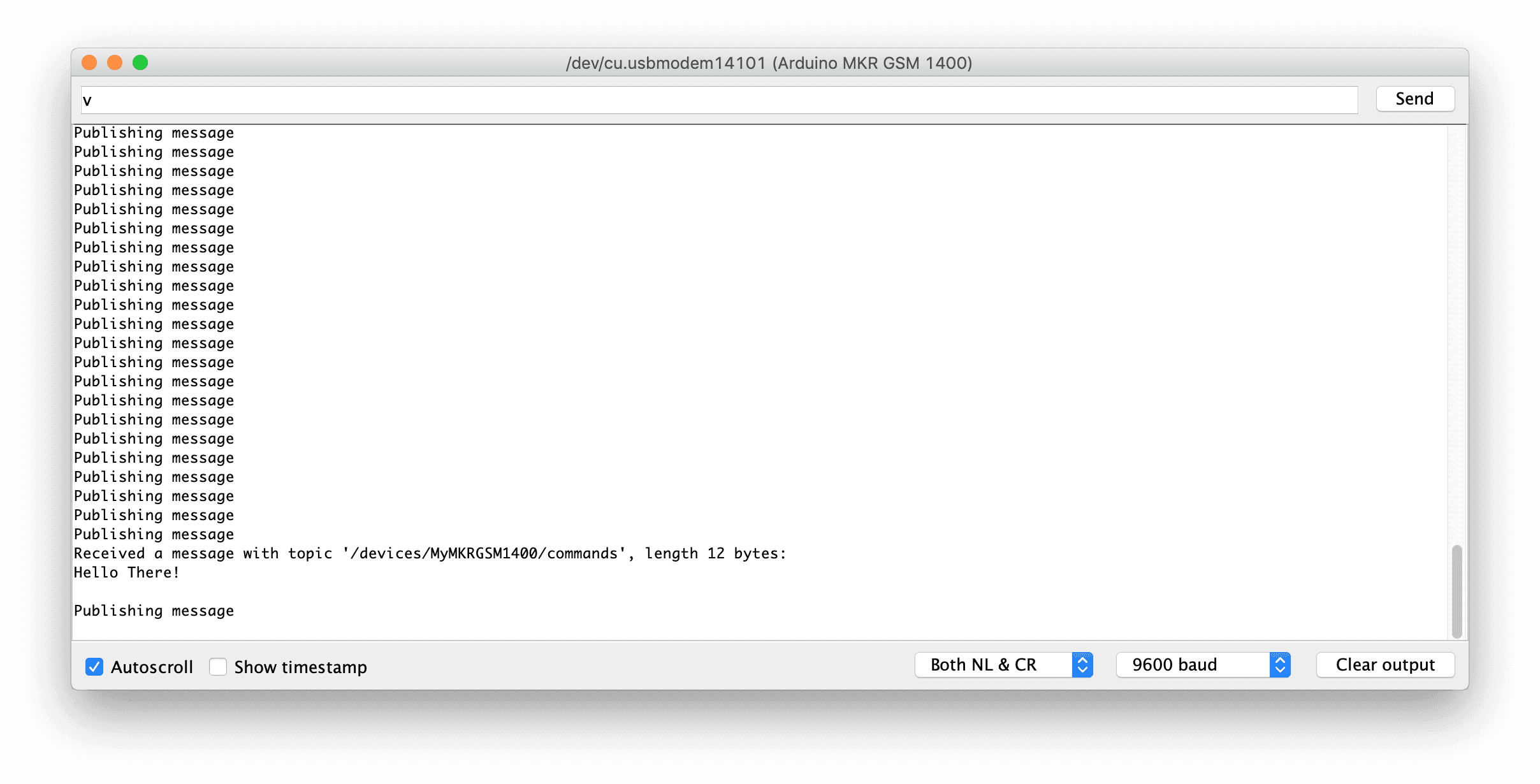
Once the board receives the message it will print it on the Serial Monitor.
To view the messages the board is sending, click "Configuration & state history" tab.
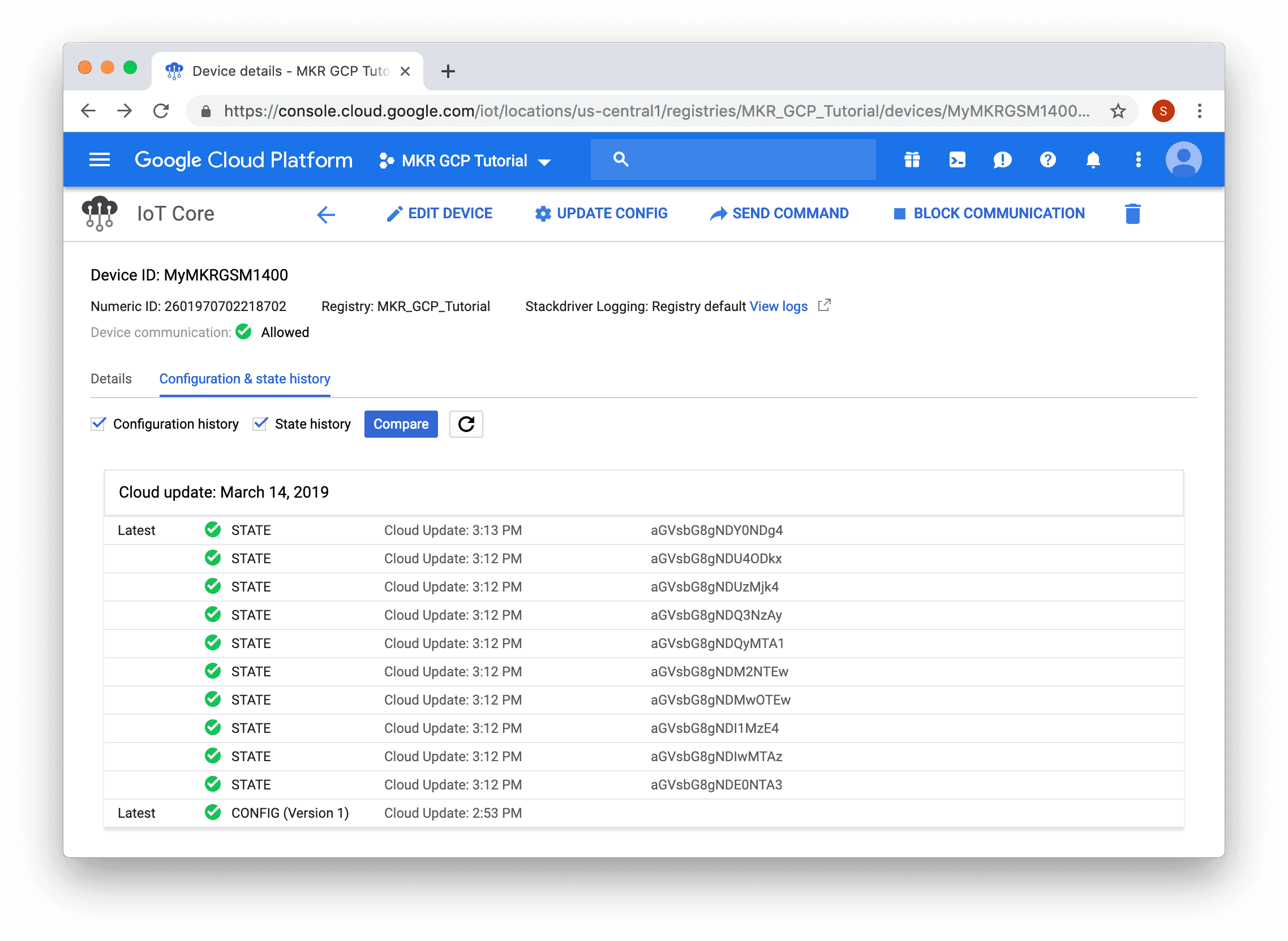
The messages will appear in Base64 encoded format, to view the value click and entry in the list and select the "Text" radio button.

In the screenshot above, the board was sending a "hello 464488" value, the 464488 value is the result of the millis() function on the board.
Conclusion
In this tutorial, we covered how to securely use an Arduino MKR GSM 1400 board with GCP IoT Core. A signed JWT was used to authenticate with GCP IoT Core using the MQTT protocol with the ATECC508A or ATECC608A storing the private key used to sign the JWT. MQTT messages were sent to and from the board.
This is just the beginning, you can use GCP IoT Core with many of the other services GCP provides!
Suggested changes
The content on docs.arduino.cc is facilitated through a public GitHub repository. You can read more on how to contribute in the contribution policy.
License
The Arduino documentation is licensed under the Creative Commons Attribution-Share Alike 4.0 license.