Sigfox Event Trigger with MKR FOX 1200
Learn how to register a button press made on the MKR FOX 1200 in the Sigfox backend portal.
This example for a MKR Fox 1200 device allows you to use the board's low power features and the SigFox's backend utilities to send an email to a configured address when an event is triggered.
Hardware Required
- MKR FOX 1200
- Antenna (link to store)
- Jumper wires
- 2x pushbuttons
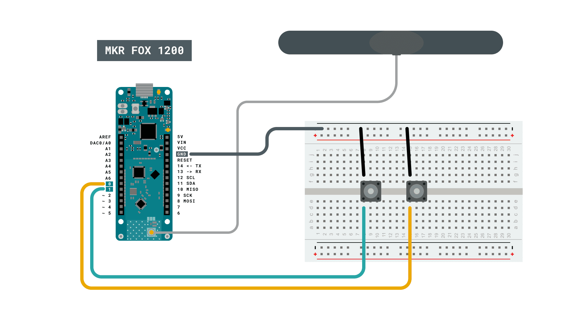
Circuit
Connect the antenna to the MKR FOX 1200 board, and follow the circuit diagram to connect the buttons.
Programming the Board
In
setup()1void setup() {2
3 if (!SigFox.begin()) {4
5 //something is really wrong, try rebooting6
7 reboot();8
9 }10
11 //Send module to standby until we need to send a message12
13 SigFox.end();14
15 // attach pin 0 and 1 to a switch and enable the interrupt on voltage falling event16
17 pinMode(0, INPUT_PULLUP);18
19 LowPower.attachInterruptWakeup(0, alarmEvent1, FALLING);20
21 pinMode(1, INPUT_PULLUP);22
23 LowPower.attachInterruptWakeup(1, alarmEvent2, FALLING);24}The
loopIn this way we can parse the message (backend side) and send a custom email.
You can find the complete code below:
1/*2
3 SigFox Event Trigger tutorial4
5 This sketch demonstrates the usage of a MKRFox12006
7 to build a battery-powered alarm sensor with email notifications8
9 A couple of sensors (normally open) should we wired between pins 1 and 2 and GND.10
11 This example code is in the public domain.12
13*/14
15#include <SigFox.h>16#include <ArduinoLowPower.h>17
18// Set debug to false to enable continuous mode19// and disable serial prints20int debug = true;21
22volatile int alarm_source = 0;23
24void setup() {25
26 if (debug == true) {27
28 // We are using Serial1 instead than Serial because we are going in standby29
30 // and the USB port could get confused during wakeup. To read the debug prints,31
32 // connect pins 13-14 (TX-RX) to a 3.3V USB-to-serial converter33
34 Serial1.begin(115200);35
36 while (!Serial1) {}37
38 }39
40 if (!SigFox.begin()) {41
42 //something is really wrong, try rebooting43
44 reboot();45
46 }47
48 //Send module to standby until we need to send a message49
50 SigFox.end();51
52 if (debug == true) {53
54 // Enable debug prints and LED indication if we are testing55
56 SigFox.debug();57
58 }59
60 // attach pin 0 and 1 to a switch and enable the interrupt on voltage falling event61
62 pinMode(0, INPUT_PULLUP);63
64 LowPower.attachInterruptWakeup(0, alarmEvent1, FALLING);65
66 pinMode(1, INPUT_PULLUP);67
68 LowPower.attachInterruptWakeup(1, alarmEvent2, FALLING);69}70
71void loop()72{73
74 // Sleep until an event is recognized75
76 LowPower.sleep();77
78 // if we get here it means that an event was received79
80 SigFox.begin();81
82 if (debug == true) {83
84 Serial1.println("Alarm event on sensor " + String(alarm_source));85
86 }87
88 delay(100);89
90 // 3 bytes (ALM) + 4 bytes (ID) + 1 byte (source) < 12 bytes91
92 String to_be_sent = "ALM" + SigFox.ID() + String(alarm_source);93
94 SigFox.beginPacket();95
96 SigFox.print(to_be_sent);97
98 int ret = SigFox.endPacket();99
100 // shut down module, back to standby101
102 SigFox.end();103
104 if (debug == true) {105
106 if (ret > 0) {107
108 Serial1.println("No transmission");109
110 } else {111
112 Serial1.println("Transmission ok");113
114 }115
116 Serial1.println(SigFox.status(SIGFOX));117
118 Serial1.println(SigFox.status(ATMEL));119
120 // Loop forever if we are testing for a single event121
122 while (1) {};123
124 }125}126
127void alarmEvent1() {128
129 alarm_source = 1;130}131
132void alarmEvent2() {133
134 alarm_source = 2;135}136
137void reboot() {138
139 NVIC_SystemReset();140
141 while (1);142}Backend Configuration
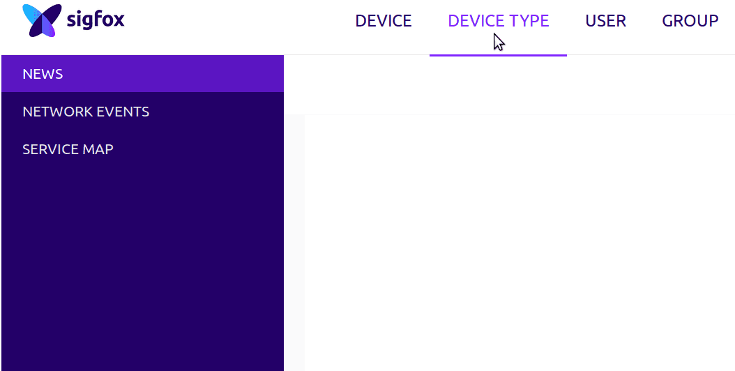
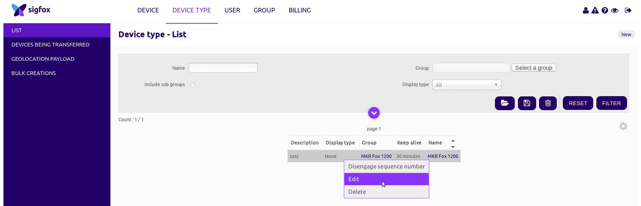
To configure the backend to send an email you have to access your control panel, click on Device Type, select MKR Fox 1200 from the list and click edit.
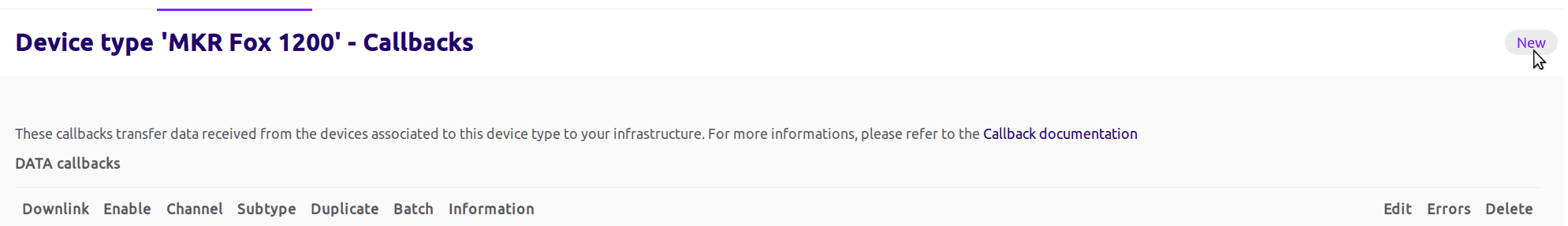
Once logged in you have to navigate to callbacks and click on new (top right corner)
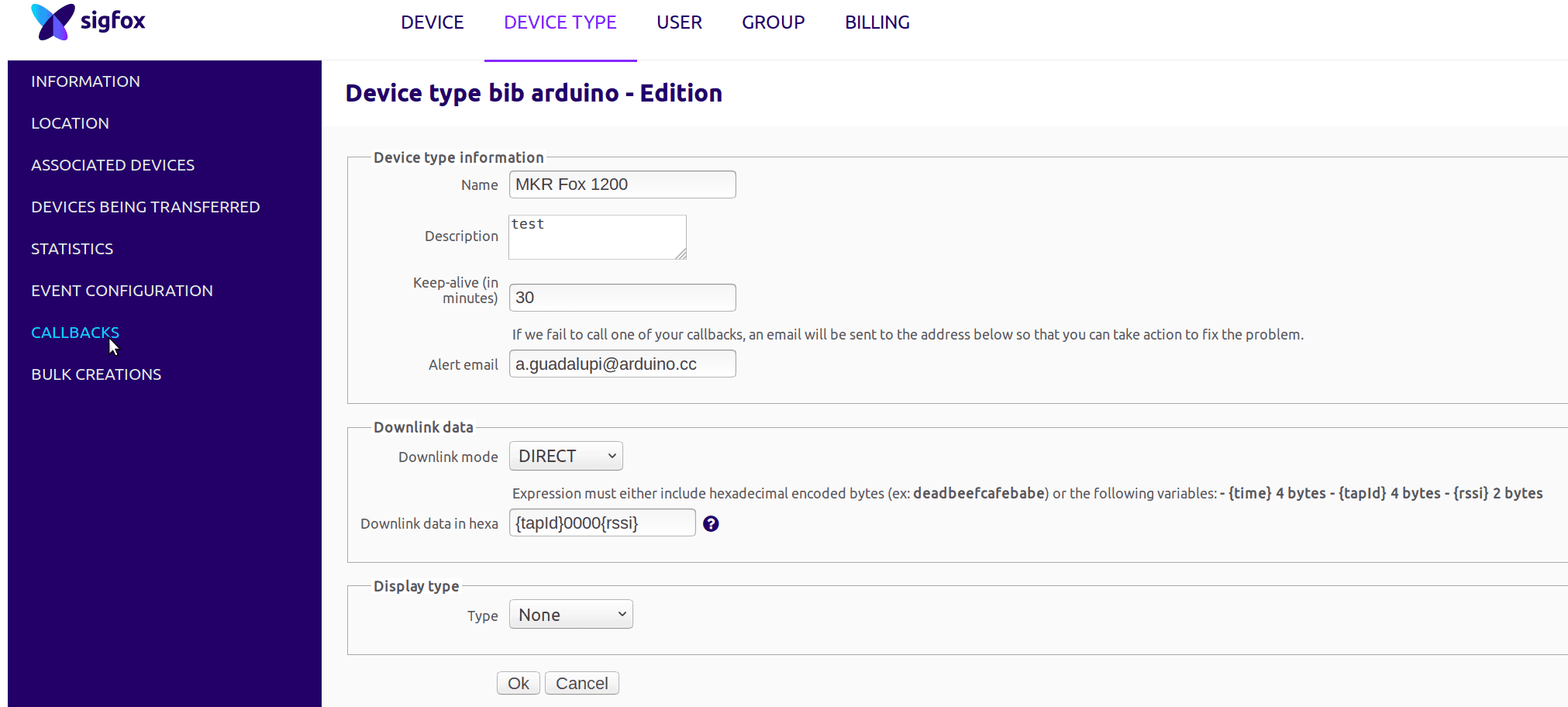
Now you can edit the email parameters as shown in the image
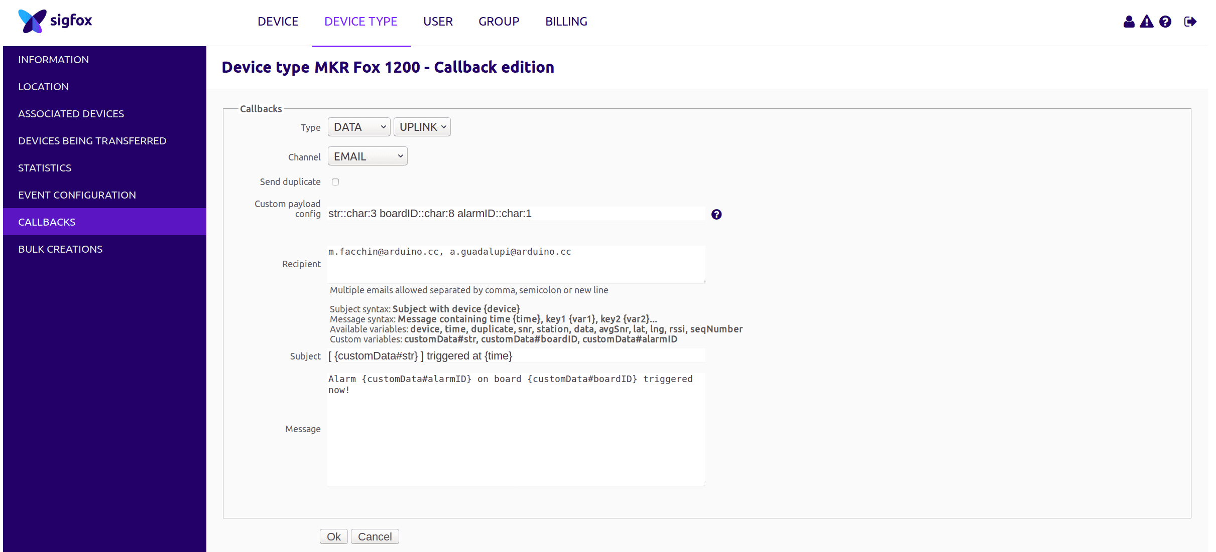
In the Custom payload config you can read:
str::char:3 boardID::char:8 alarmID::char:1
This means that in the 12 bytes of received message (from left to right):
- str::char:3
3 characters are assigned to a variable called str
- boardID::char:8
8 chars are assigned to the boardID variable
- alarmID::char:1
1 char is assigned to the alarmID variable
Since you have assigned these values to these variables, you can now use them within your mail body and you can see in the Subject and Message field!
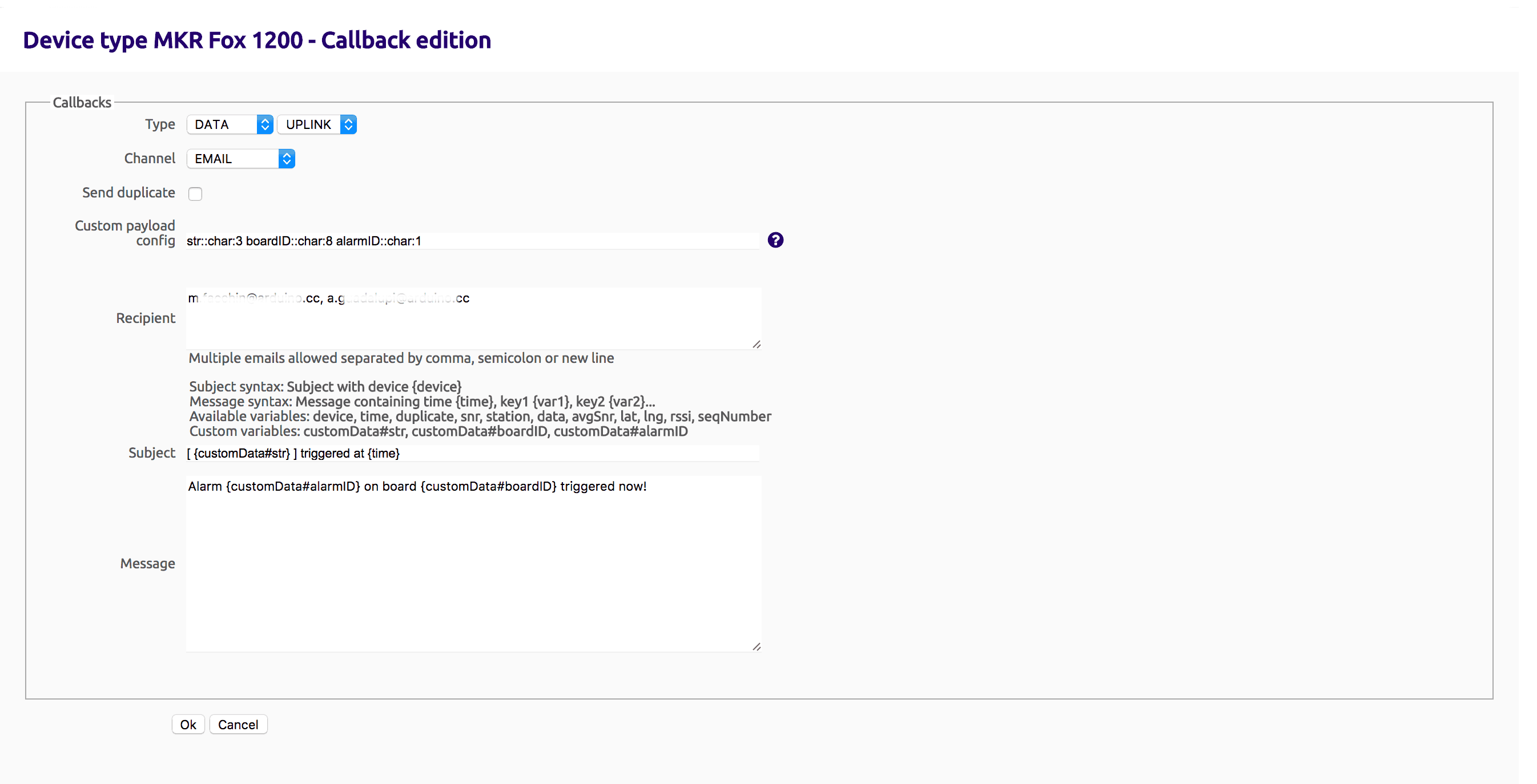
To configure this callback:
Type field: DATA - UPLINK
Channel: EMAIL
Custom payload config: str::char:3 boardID::char:8 alarmID::char:1 (as explained before) Recipient: write your recipient email address, if you want more than one, use comma separated format.
Subject: you can use a custom data value or a standard variable like time, snr, station, data as shown just before the subject line
Message: same as Subject, you can use free text and some custom or standard variables.
Now click on OK to store your callback and you are done! The very next time your alarm will trigger, you will receive an email!
Conclusion
In this example we configured the Sigfox backend to send an email to a configured email address, using the MKR FOX 1200.
Suggested changes
The content on docs.arduino.cc is facilitated through a public GitHub repository. You can read more on how to contribute in the contribution policy.
License
The Arduino documentation is licensed under the Creative Commons Attribution-Share Alike 4.0 license.